



 Home
Home
A BESS Battery Energy Storage System Coordinates More Than Stored Energy
A BESS battery energy storage system combines batteries, power electronics, controls and site interfaces so that stored energy can serve a defined electrical task.
The cabinet is the visible part of a larger arrangement. Energy must move through electrical equipment, while measurements and commands move through a control network. Understanding those two paths helps explain why a battery capacity figure alone cannot describe system behaviour. It also makes discussions about grid connection, renewable integration and backup operation more precise without turning an introductory explanation into an equipment-sizing exercise.
Start With Two Paths Through The System
The Electrical Path Carries Power
Cells are assembled into modules, racks or other arrangements appropriate to the design. Their direct-current connection reaches equipment that controls or converts the electrical exchange with the rest of the site. In an AC-connected arrangement, power conversion bridges the DC battery side and the AC system. Protection, switching, measurement and supporting equipment are part of the route even when a simplified diagram leaves them out.
The BESS product category shows system offerings, but the boundaries of a particular supply package still need to be read from its technical documents. A cabinet image does not reveal every included component or connection responsibility. Some projects package several functions together, while others distribute them across cabinets, rooms or site equipment. The functional question is what each part does, not whether it occupies a separate enclosure.
The Information Path Coordinates Decisions
Sensors and controllers provide information about the battery, converter and site. Commands may originate from a local controller, a site energy management system or an external operator, subject to the design. The control hierarchy determines how those instructions are interpreted and which constraints take priority. A requested discharge is therefore not identical to an unconditional instruction to deliver power under every circumstance.
The Energy Market Authority's energy storage handbook describes batteries, battery management, thermal management, power conversion and energy management as connected functions. That older handbook is useful for stable introductory terminology; it does not replace current project standards or local connection requirements. The key idea is that a system must coordinate the condition of its components with the electrical service it is expected to provide.
Separate Battery Management From Site Management
Battery Management Follows Battery Conditions
A battery management system, commonly called a BMS, monitors relevant battery conditions and supports operation within the design's permitted limits. The exact measurements, protective actions and architecture depend on the product. Temperature, voltage and current information can influence what operation is permitted. The BMS is not simply a dashboard; its role is connected to the battery's operating conditions and protective strategy.
State of charge is an estimate of remaining charge relative to a defined reference, not a direct reading of future energy available to every load. It must be interpreted alongside the permitted range and other conditions. A low or high limit can restrict an instruction even when the site would benefit economically from another action. This is one reason an energy schedule must remain subordinate to relevant equipment constraints.
Energy Management Follows The Site Objective
An energy management system, or EMS, coordinates operation toward a site objective. That may involve renewable generation, demand, tariffs, an export constraint or a planned reserve, depending on the project. The EMS overview provides a site-specific starting point for understanding the offered function. Its general description should not be read as proof that every integration, communication protocol or control feature is included in every package.
A clear control hierarchy helps separate the desired outcome from the permitted action. The EMS may request an operating point, while lower-level equipment applies its own available limits. The practical question is how the system reports a reduced capability and what the higher-level controller does next. A system that cannot meet a requested value should not leave its operator guessing whether the cause is battery condition, converter status, a communications issue or a site constraint.
Understand Power Conversion As An Interface
Conversion Has Both An Electrical And A Control Role
The power conversion system, often shortened to PCS, connects the battery's electrical form to the relevant site network. In a common AC-connected design it manages conversion between DC and AC. Its capability must be interpreted with the connection arrangement and operating conditions. Equipment nameplates and a one-line diagram answer different questions: one describes a component, while the other shows how the project connects components.
Power conversion equipment also receives commands and reports status. Its operating state may determine whether the system is ready, starting, charging, discharging, restricted or stopped. A communications message saying that a command was received is not proof that the requested electrical output occurred. Meaningful monitoring connects the command, equipment status and measured result at an identified measurement point.
The engineering service page is relevant when moving from this functional view to a project design. At that stage, connection drawings, interface definitions and responsible parties matter more than a generic block diagram. The introductory distinction remains useful: power equipment moves energy, while controls decide and report how that movement is managed.

Read The Operating State Before Interpreting A Dashboard
A Single Number Does Not Describe Readiness
A BESS battery energy storage system can have stored energy while being unavailable for the requested service. A stopped converter, maintenance isolation, an unresolved alarm or an unavailable site connection can change what is possible. These conditions are examples of why readiness needs an explicit definition. Operators need to know which part is unavailable and whether the system has entered a restricted or stopped condition.
The operating state should be interpreted with the time of the measurement. A stale value on a screen can look plausible even after communications have been interrupted. Good interface design distinguishes a current measurement from an old value and makes missing data visible. This does not mean every data gap requires the same response; the response belongs to the project's approved control and protection design.
Transitions Explain What Happens Between Steady Conditions
Starting, stopping and changing modes can be more informative than observing a steady power value. A transition may involve checks, permissions and a sequence of equipment actions. The approved sequence determines what happens when a required condition is absent. A system overview should therefore describe both its normal operating modes and the conditions that prevent entry into them.
| Function | Question it answers | What it does not establish alone |
|---|---|---|
| Battery monitoring | What battery conditions are observed? | Whether the whole site is ready to operate |
| Conversion status | What electrical exchange is available or occurring? | Whether the planned business objective is being achieved |
| Energy management | What operating objective is requested? | Permission to override equipment constraints |
| Site measurement | What occurs at the defined measurement point? | The cause of every deviation |
| Alarm and event record | What condition or transition was recorded? | A complete diagnosis without context |
Place The System Inside Its Electrical Environment
Grid-connected operation and operation serving an isolated network involve different design questions. The presence of a battery does not automatically mean a site can operate independently when the grid is lost. The connection arrangement, controls, protection and supporting equipment must provide the required capability. A backup claim should be checked against an actual design and defined loads rather than inferred from the energy stored.
The remote-area solution overview shows why the surrounding system matters. Generation, storage and loads need a coordinated operating approach. At an introductory level, it is enough to distinguish the service objective from the equipment list. Detailed voltage, frequency, protection and switching decisions require project engineering and the applicable local requirements.

- Follow the request.
- Check the permitted action.
- Compare the measured result.
A useful system explanation follows the request, the permitted action and the measured result. Those three are related, but they are not interchangeable.
Use Records To Connect Components With Behaviour
Technical service documents become easier to read when each is tied to a question. A component datasheet describes an item; an interface schedule describes information or electrical boundaries; a control narrative explains behaviour; and an event log records what the system reported. None replaces all the others. Together they allow an engineer or operator to trace a problem through the relevant part of the system.
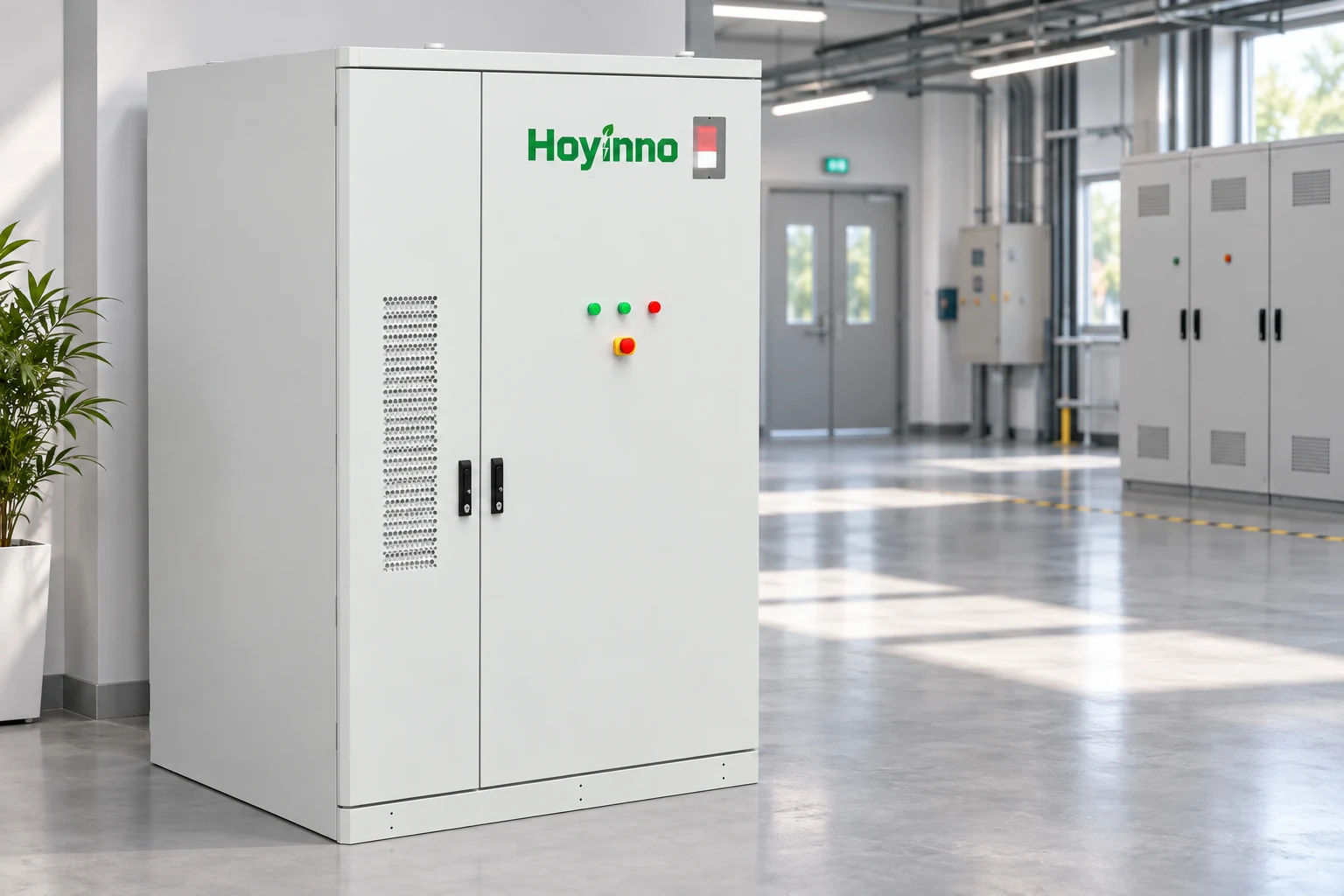
The same-site cabinet product page offers a concrete visual reference. Its model-specific information belongs to that offering and should not be generalised to every BESS configuration. Likewise, a generated cabinet illustration can support recognition of an enclosure but cannot establish battery chemistry, internal arrangement or installed project performance.

A BESS battery energy storage system is best understood as coordinated functions within a defined project boundary. The battery stores energy, the electrical interface manages its exchange, and the controls connect objectives with permitted operation. Reading those relationships first makes later discussions of sizing, availability and performance more meaningful. The next conceptual step is to map one proposed service through that chain and identify the measurements that would demonstrate its behaviour.
Frequently Asked Questions
Are BMS And EMS The Same Function?
No. Battery management focuses on battery conditions and permitted operation, while energy management coordinates a wider site objective. Their exact implementation varies, but a clear interface should explain how requests, limits and status pass between them.
Does A Charged Battery Mean The System Is Ready?
No. Readiness also depends on the converter, connection, controls and other required conditions. Stored energy is one part of the picture, and the operating state explains whether it can serve the requested task at that time.
Can Every BESS Supply Backup Power?
That capability should be confirmed in the project design. A battery and converter do not automatically provide the connection arrangement, controls and protection needed for independent operation of the intended loads.
Why Can A Command Differ From Measured Output?
A command expresses a request. Equipment limits, operating conditions or a site constraint may restrict the action. Compare the request with status, reported limits and measurements at the defined point before drawing a conclusion.
What Is The Best First Document To Read?
A functional overview or system diagram can establish the boundaries and major components. Read it with the control narrative so the physical connections and decision sequence are understood together, then consult component documents for specific details.
 Which Limits Define The Usable Output Of A Battery Storage System?
  Address: A401, Junxu Junchuang Park, 03A Qingyi Road, Nanhai District, Foshan City, Guangdong Province, China