



 Home
Home
How Does A Modular Energy Storage System Scale Without Fragmenting Control?
A Modular Energy Storage System scales through repeatable energy blocks only when controls, protection, thermal limits, and commissioning remain coordinated. Adding cabinets can increase energy or power, but physical repetition alone does not create a coherent plant. The site controller must know what every block can safely deliver, protection must isolate a fault without confusing the rest of the system, and project design must preserve predictable behavior as the installation grows.
Modularity Begins With a Stable System Boundary
Separate the Repeatable Block From Shared Plant Functions
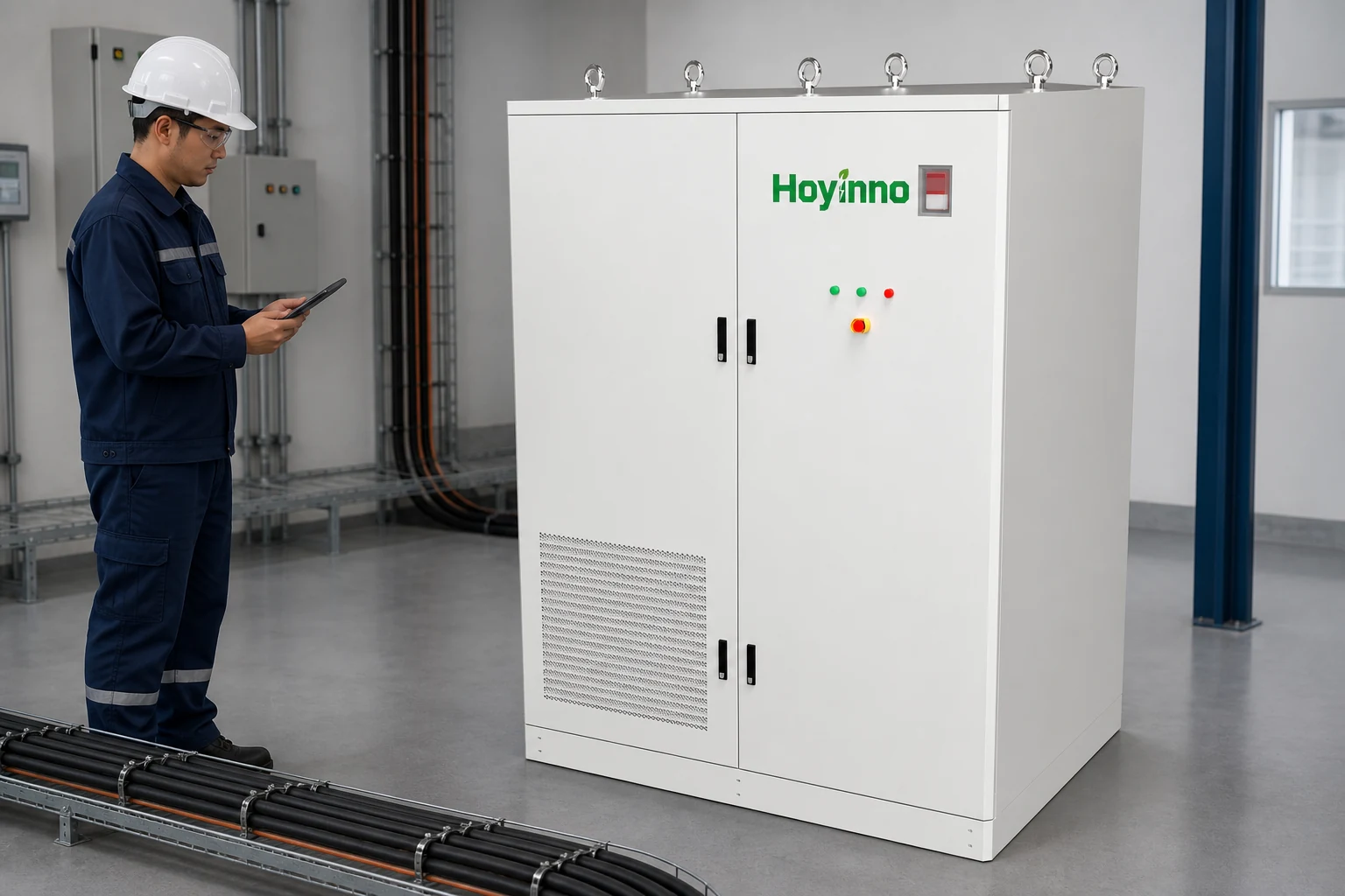
A useful architecture starts by naming what repeats. An energy block may include cells, modules, racks, battery management, a cabinet enclosure, thermal management, fire detection, local protection, and sometimes its own power conversion. Other functions may remain shared: medium-voltage equipment, a transformer, plant controller, metering, auxiliary supply, network gateway, and site-level emergency logic. The boundary should be represented consistently in the single-line diagram, communication map, equipment list, and control narrative.
The BESS product overview provides context for cabinet, container, and project configurations. For an actual design, the EPC team should distinguish nameplate energy from usable energy, nominal power from continuously available power, and component quantity from functional redundancy. A repeated enclosure is only one layer of modular battery architecture; the electrical and software dependencies between enclosures decide whether the plant can expand cleanly.
Use Interface Documents as the Scaling Contract
Every boundary needs declared inputs, outputs, operating ranges, and failure behavior. Electrical interfaces include voltage window, current limits, short-circuit contribution, grounding, isolation, and auxiliary load. Communication interfaces include protocol, register definitions, update rates, time synchronization, alarms, cybersecurity responsibilities, and behavior after a lost link. Mechanical interfaces include lifting, clearances, foundation load, cable entry, drainage, ventilation, and service access.
When the same interface schedule is applied to each block, design changes become easier to control. When interface assumptions remain only in separate vendor drawings, each expansion can introduce a different cable rule, address scheme, alarm name, or shutdown sequence. That fragmentation increases commissioning time and makes later troubleshooting depend on individual memory rather than controlled documentation.
Energy and Power Scale Through Different Paths
Match the Expansion Pattern to the Duty Cycle
Increasing energy duration usually adds battery capacity, while increasing power requires adequate conversion, conductors, switchgear, transformer capacity, and grid agreement. Some products couple a fixed amount of battery energy with a power-conversion channel; others allow battery blocks to share a converter within defined limits. The project model must therefore show how an added block changes usable kilowatt-hours, charge and discharge kilowatts, efficiency, auxiliary demand, and operating reserve.
A 522 kWh cabinet page illustrates one equipment-level form, but a project decision still depends on the required duty cycle and connection topology. Peak shaving, solar shifting, backup support, and microgrid operation impose different duration, response, reserve, and cycling expectations. Scalable battery capacity is meaningful only when the rest of the path can accept it and the dispatch objective can use it.
| Scaling question | Battery layer | Shared plant layer | Verification output |
|---|---|---|---|
| More energy duration | Additional usable energy and state estimation | Auxiliary supply, controls, and thermal duty | Updated operating envelope and energy test |
| More active power | Permitted battery current and voltage range | PCS, bus, switchgear, transformer, grid limit | Power test with constraint reporting |
| More availability | Block isolation and minimum online set | Dispatch logic and maintenance reserve | Degraded-mode test |
| Future expansion | Compatible hardware and firmware baseline | Spare ways, addresses, settings, and space | Expansion interface schedule |
A Hierarchy of Controls Prevents Conflicting Commands
Coordinate Cell, Rack, Converter, and Site Limits
Control is normally hierarchical. Local battery management estimates state and protects cell or rack limits. A power conversion system regulates electrical power within its own voltage, current, and thermal envelope. An energy management or plant controller turns the site objective into commands and coordinates connection status, reserve, and grid constraints. Each layer needs authority boundaries so that a higher-level request cannot override a local safety limit.
Distributed power conversion can reduce a single failure domain and pair converters with repeated battery blocks, but it also creates more controllers, firmware versions, measurements, and communication paths. Central conversion may simplify interfaces while increasing shared dependency. The choice follows fault containment, maintenance, efficiency, voltage, and expansion sequence.
Make Degraded Operation Explicit
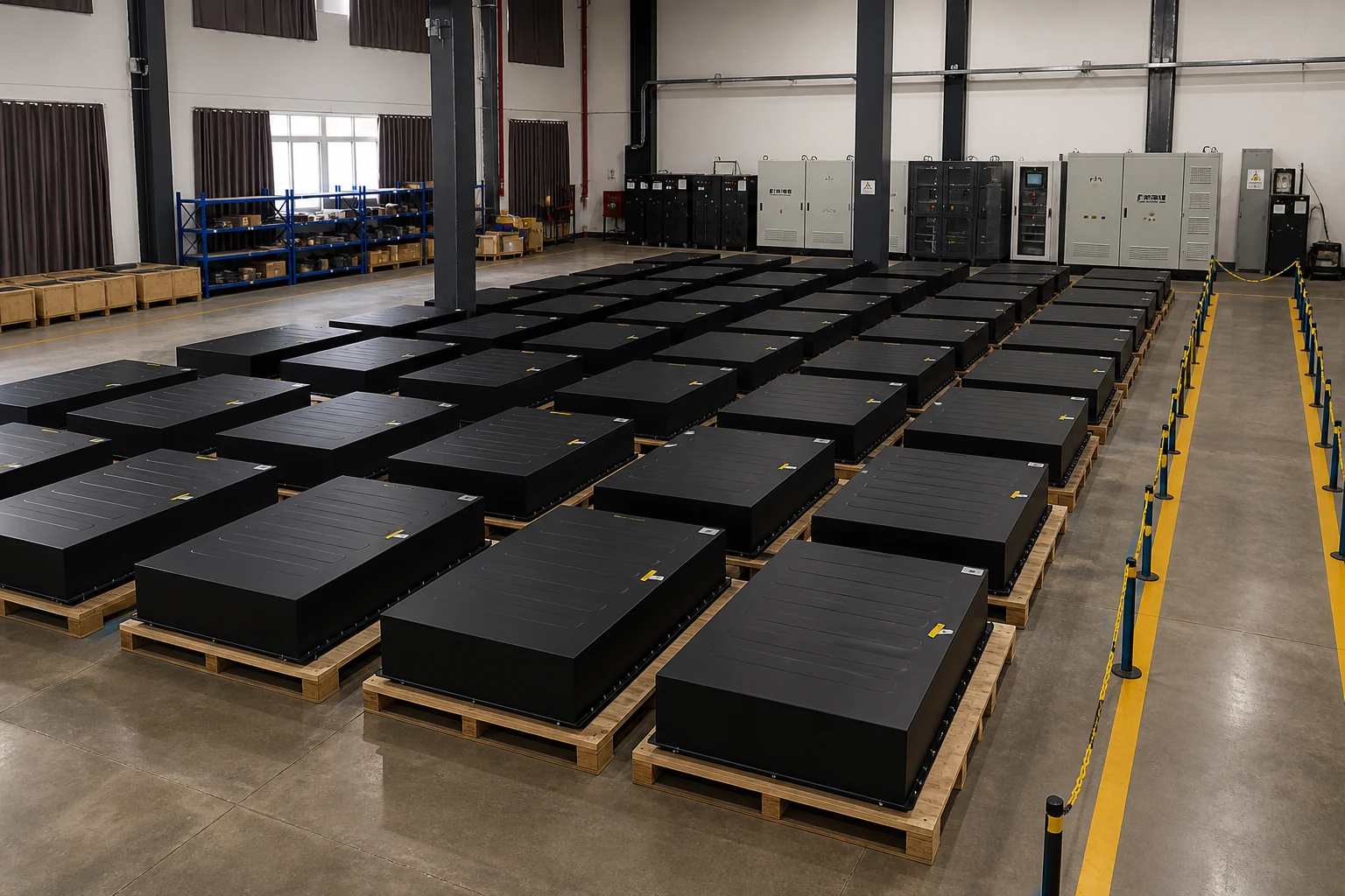
A Modular Energy Storage System should state what happens when one block is unavailable, derated, isolated, or disconnected from communications. The controller needs to calculate remaining energy and power from the online set, not from the original nameplate total. It should avoid pushing healthy blocks beyond their current or thermal limits to compensate. Operators need clear alarms that distinguish a lost measurement, a protective trip, a scheduled outage, and an intentional maintenance state.
Degraded-mode logic is also a commissioning target. Test whether the plant continues safely with one block removed, whether it reconnects only after defined checks, and whether historian data preserves the event sequence. The same logic helps EPC teams plan staged energization and future expansion without treating each construction phase as a new control system.
Protection Must Scale With Fault Energy and Topology
Coordinate Isolation Without Hiding a Common Cause
Adding blocks changes available fault current, cable routing, protective-device coordination, arc-flash conditions, and the number of isolation points. The electrical study should use the actual topology and equipment data, including converter behavior where applicable. A local device should isolate the intended fault zone while upstream protection remains coordinated. Shared DC or AC buses, common auxiliary power, network switches, cooling distribution, and emergency-stop circuits deserve special attention because a single failure can affect many otherwise independent blocks.
IEC TS 62933-5-1 provides general safety considerations for grid-integrated electrical energy storage systems, while local codes and project requirements determine the enforceable design. UL 9540A is a test method for evaluating thermal-runaway fire propagation; a report must be interpreted for the tested cell, module, unit, installation parameters, and intended use. It is not a generic certification badge for every configuration derived from a product family.
Connect Thermal Limits to Dispatch
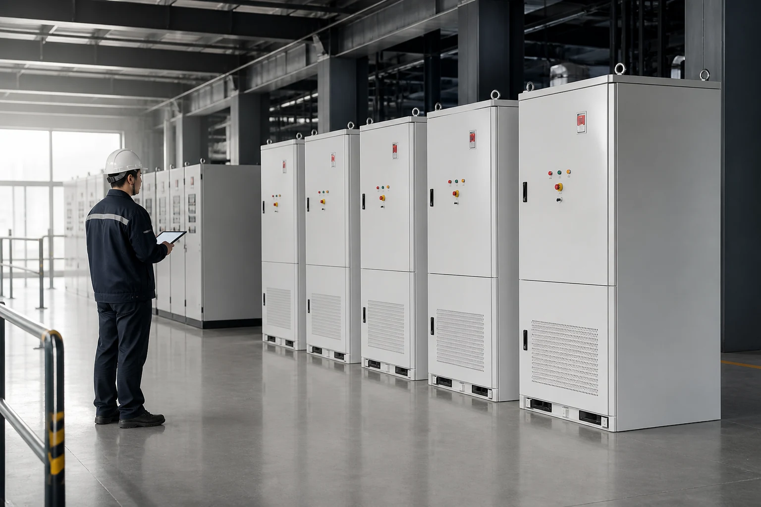
Ambient temperature, solar loading, humidity, dust, altitude, and available cooling capacity affect how much power a block can sustain. A hot-climate project in Southeast Asia, Africa, or the Middle East should not assume that a laboratory nameplate remains continuously available outdoors. The thermal model needs enclosure losses, HVAC or liquid-cooling performance, auxiliary demand, spacing, recirculation, and the failure response of cooling components.
Thermal alarms should feed the operational envelope instead of remaining isolated maintenance events. If one cabinet approaches a limit, the controller can derate that block, redistribute power within safe limits, or reduce plant output. The governing documents should explain priority and recovery behavior. This preserves comparable aging and avoids turning a local cooling constraint into a hidden imbalance across the installation.
Commissioning Proves the Integrated Behavior
Test One Block, Then the Interactions Between Blocks
Factory acceptance can verify assembly, wiring, insulation, local functions, communications, alarms, and configured parameters. Site acceptance adds installed cables, grounding, transformer, switchgear, protection settings, network, auxiliaries, and grid interface. The commissioning plan should map each design requirement to a test, expected result, record, responsible party, and acceptance authority.
After one block passes, test plant interactions. In a Modular Energy Storage System, commands should ramp across the online set, totals should reconcile, an isolated block should leave available capacity, trips should propagate only as designed, and restoration should follow a controlled sequence. The system solution pages can support architecture discussions, while project acceptance must use approved documents and calibrated measurements.
Plan Expansion Before the First Phase Is Frozen
Future growth requires more than an empty plot. Reserve space, foundation routes, switchgear ways, intended transformer margin, network addresses, controller licenses, protection ranges, and auxiliary capacity. Define compatible hardware and firmware, and preserve configuration baselines for later additions.
The modular solution context is most useful when paired with an expansion sequence and interface schedule. The project team can identify outages, construction isolation, setting changes, revised grid studies, and final acceptance. This keeps modular battery architecture, scalable battery capacity, and distributed power conversion aligned through later phases.

Frequently Asked Questions
Is a modular system the same as a containerized system?
Not necessarily. Modularity describes repeatable functional blocks and controlled interfaces; containerization describes an enclosure and transport form. A container can hold modular racks, and cabinet blocks can form a modular outdoor plant. The important comparison is the electrical, control, protection, thermal, and service boundary.
Can energy capacity be increased without changing power equipment?
Sometimes, if the approved topology allows more battery energy behind existing conversion and connection equipment. The result may increase duration without increasing maximum power. Engineers must verify the cabinet interface, voltage window, current sharing, auxiliaries, protection, thermal behavior, licenses, and grid limits.
Why can identical cabinets show different available power?
State of charge, temperature, state of health, alarms, maintenance status, voltage limits, and communication quality can all change a block's current capability. The plant controller should calculate availability from current block limits and explain the governing constraint to operators.
What should an EPC team include in commissioning acceptance?
Include approved drawings and settings, equipment identification, local checks, protection tests, communication validation, energy and power tests, degraded modes, emergency sequences, deviations, training, and a signed requirements traceability matrix.
Coherent scaling is therefore measured by predictable interfaces and verified behavior, not by cabinet count. A sound design keeps the energy blocks repeatable while making shared dependencies visible, coordinates every local limit with plant dispatch, and proves both normal and degraded operation at each expansion phase.
 What Makes A Utility Scale Battery Energy Storage System Grid-Ready?
  Address: A401, Junxu Junchuang Park, 03A Qingyi Road, Nanhai District, Foshan City, Guangdong Province, China