



 Home
Home
Why Does A Liquid Cooled BESS Cabinet Need Layered Thermal Control?
A Liquid Cooled BESS Cabinet needs a continuous thermal path, reliable sensors, coordinated controls, and site-level commissioning. Useful thermal management depends on a chain of layers: heat must move predictably from cells into cold plates; pumps and valves must maintain flow; sensors must describe the actual state; controls must respond without creating instability; and the enclosure, fire strategy, electrical protection, and site design must remain compatible with those actions. Weakness in any layer can erase the benefit of the others.
Heat Begins at the Cell but Risk Propagates Through the System
Distinguish Average Temperature From Local Hot Spots
Every charge and discharge cycle generates heat. The amount and location vary with current, resistance, state of charge, age, ambient condition, and manufacturing variation. A pack can have an acceptable average while individual modules run hotter. That difference matters because electrochemical behavior, available power, degradation, and protection margins are temperature-dependent. The broader BESS product family still requires configuration-specific thermal evidence.
Air systems transfer heat through moving air and heat exchangers. Liquid systems bring a coolant path closer to cells or modules, typically through plates, manifolds, hoses, and a liquid cooling system. The higher heat capacity of a liquid loop can support compact layouts and closer temperature control, but it adds interfaces that must be engineered: seals, joints, pumps, valves, fill points, sensors, insulation, and service procedures. Liquid cooling changes the failure modes; it does not remove the need to manage them.
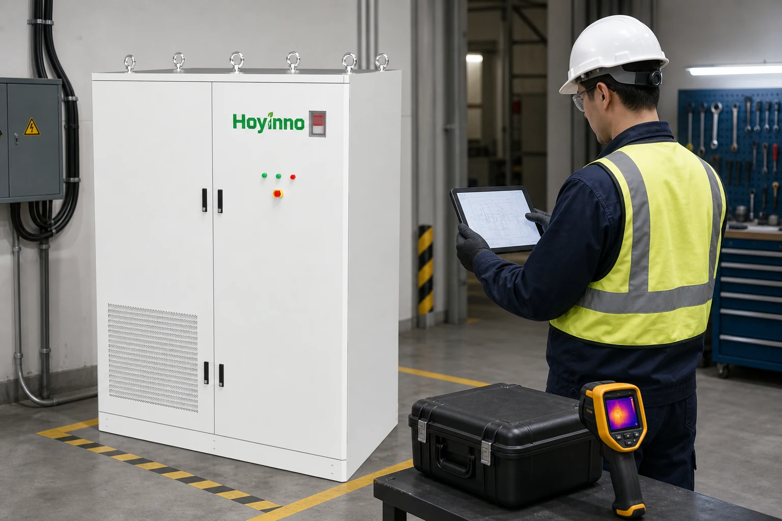
The same-site 522kWh cabinet page lists 522kWh energy, 250kW power, a 3.2V/314Ah LFP cell, liquid cooling for the battery side, forced-air cooling for the converter, IP54 protection, and communication interfaces. These are model-specific values, not a substitute for the project's approved datasheet, drawings, and tests. The manufacturer homepage provides context but not project acceptance evidence.
Layer One: Build a Continuous Thermal Path
Control Every Interface From the Cell to the Heat Exchanger
The first layer is physical heat transfer from the cell to the coolant. A typical path includes the cell surface, module structure, thermal interface material, cold plate, circulating fluid, and a heat-rejection device. Contact pressure, interface thickness, plate geometry, channel design, coolant properties, and flow distribution determine how much resistance the path introduces. Small installation differences can create unequal performance between modules.
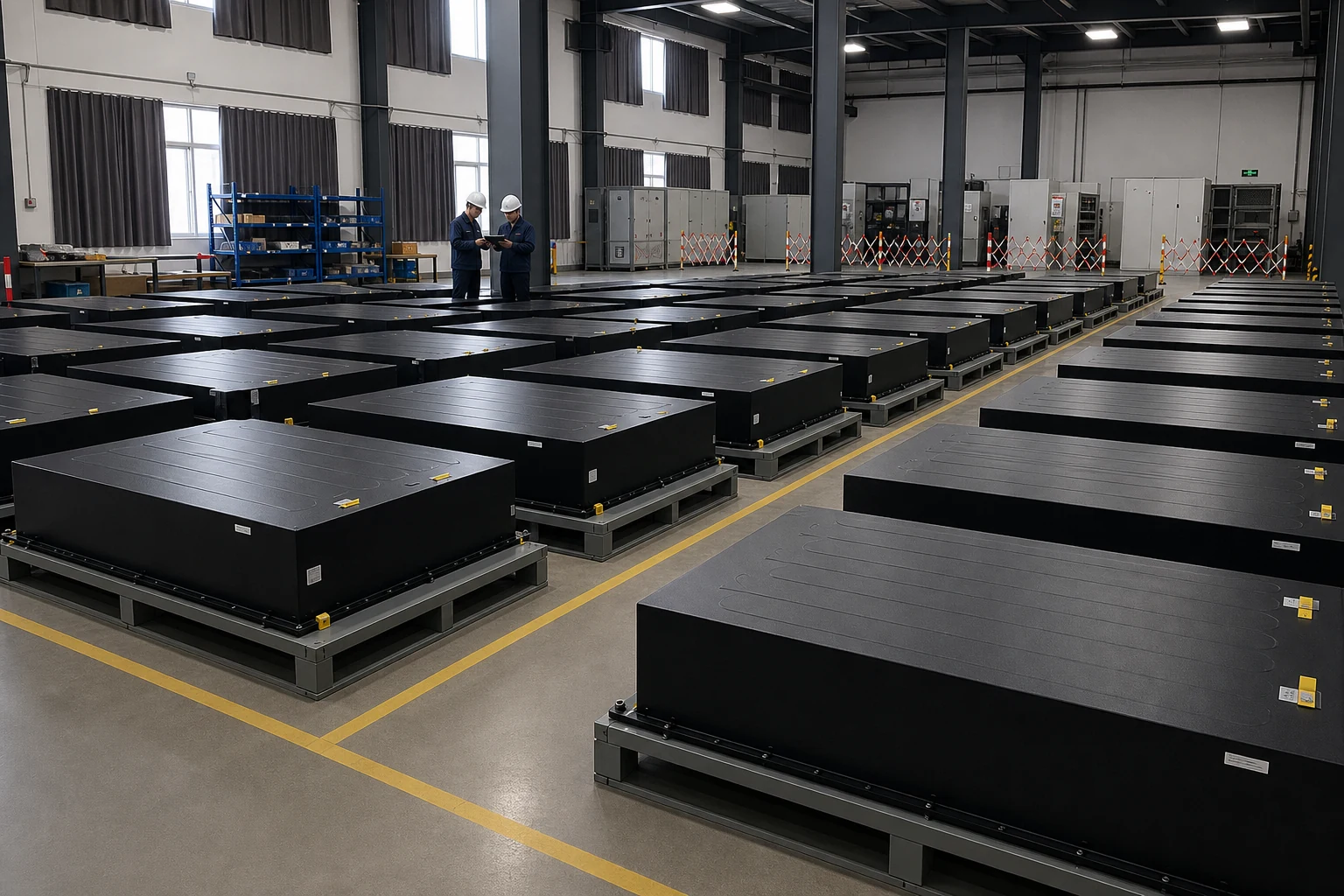
Cold-plate design must also account for electrical isolation and mechanical movement. Cells and modules can expand, settle, or experience vibration. The thermal interface must retain contact without imposing harmful stress. Leak containment should consider where fluid would travel under gravity, whether energized parts sit below joints, and how a small seep differs from a large hose failure. Drainage, barriers, drip sensing, and shutoff logic are complementary design measures.
Layer Two: Measure the State, Not Just One Temperature
Place Sensors Around Credible Thermal and Fluid Faults
A controller cannot regulate what it cannot observe. Temperature sensors need enough coverage to represent both average conditions and plausible hot spots. Coolant supply and return temperature, flow or pressure, pump state, valve position, ambient temperature, humidity, door status, and leak detection can help distinguish a high-load condition from a cooling fault. Sensor placement should be justified by thermal analysis and verified by test, not selected only because a point is easy to wire.
Accuracy is only one part of measurement quality. Response time, calibration, drift, fault detection, filtering, and synchronization also matter. A slow sensor may report a safe value after a local temperature has moved. Retained trends should compare commanded cooling with actual response, identify imbalance, and connect thermal management design to behavior. The industry article archive offers background, while commissioning data must prove the installed system.
Layer Three: Coordinate the BMS, Thermal Controller, and EMS
Define Command Priority, Derating, and Fail-Safe States
Thermal hardware becomes effective through control. The battery management system observes cell conditions and enforces battery limits. A local thermal controller may operate pumps, fans, compressors, heaters, and valves. The energy management system schedules cabinet power according to site objectives. These layers need explicit ownership of commands, limits, alarms, and fail-safe states.
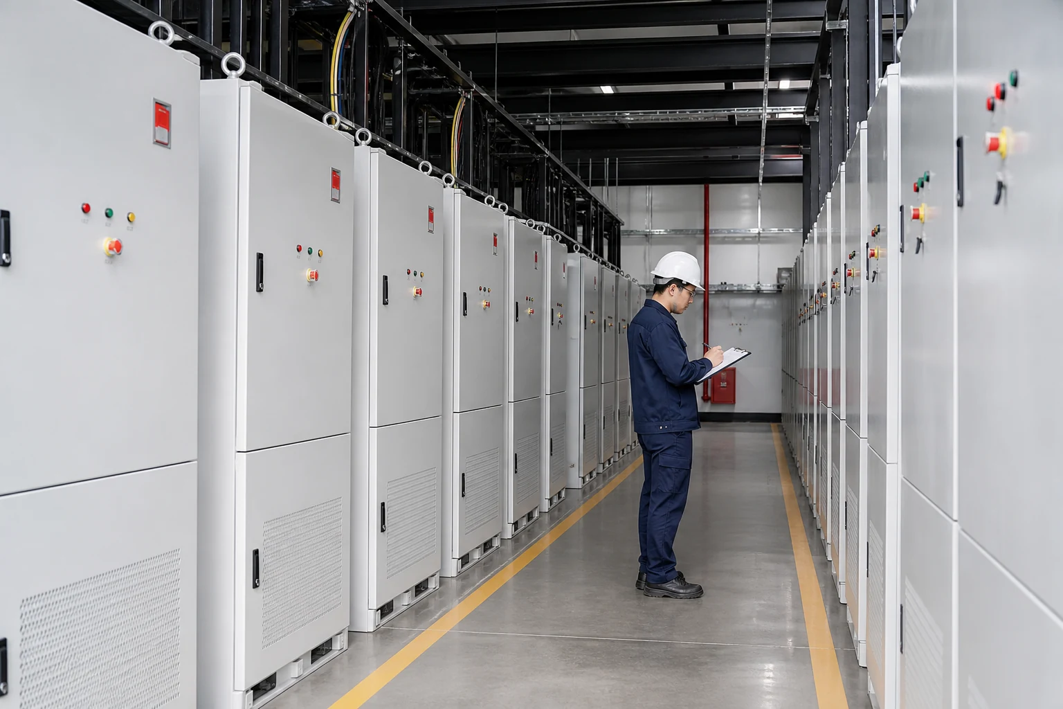
Consider a rising module temperature. The local controller may increase coolant flow; the BMS may request power derating; the EMS may be attempting to discharge at maximum site demand. The interface specification must define which request has priority, how fast it propagates, what happens when communication is lost, and how the system recovers. A safe derating response is often preferable to an abrupt trip, but the correct sequence depends on the hazard analysis and equipment limits.
Control stability also matters. Narrow on/off thresholds can make pumps or compressors cycle rapidly. Wide thresholds can allow unnecessary temperature excursions. Staged control, hysteresis, proportional logic, and minimum run times can help, but they must be tuned to the thermal mass and delay of the actual Liquid Cooled BESS Cabinet. Commissioning should test transitions between standby, charge, discharge, derate, fault, and recovery rather than only proving that a pump turns on.
Layer Four: Manage Leaks, Condensation, and Enclosure Conditions
Treat Fluid Escape and Dew Point as Different Hazards
Liquid and high-voltage equipment share a compact enclosure, so the fault strategy must be designed rather than implied. Review joint count and placement, rated pressure, proof testing, hose support, abrasion protection, service access, leak sensor location, drainage path, and automatic isolation. A single floor sensor may miss a leak captured on an internal shelf. A leak alarm without a defined shutdown and inspection procedure provides awareness but not control.
Condensation is different from a leak: moisture forms when a surface falls below the local dew point. Controls may need to limit coolant temperature, manage humidity, insulate surfaces, or coordinate heating. Cable penetrations, doors, vents, drains, and field conduits also affect enclosure performance. Confirm the delivered and installed rating and compare it with the example cabinet's published enclosure data.
Layer Five: Integrate Safety Standards and Site Design
Reconcile Product Certification With the Installed Configuration
Thermal management is one part of a broader safety architecture. The official record for IEC TS 62933-5-1:2017 is marked withdrawn, so it is historical background, not a current governing requirement. UL explains UL 9540 at system level, including controls and thermal components. For a Liquid Cooled BESS Cabinet, confirm the applicable edition, national adoption, certification scope, fire and electrical codes, and authority requirements. Review relevant system context without confusing an article with certification evidence.
The site can raise or lower thermal demand through solar loading, shade, dust, salt, altitude, humidity, drainage, nearby heat, and restricted airflow. Civil design should protect access and prevent runoff. If several cabinets are grouped, assess heat rejection and recirculation at array level. The cabinet category is the starting boundary; the installed array is the acceptance boundary.

Liquid cooling is not a single feature. It is a controlled path from cell heat to the environment, surrounded by measurement, software, protection, enclosure, and site layers.
Commission the Layers as One Evidence Chain
Test Normal Operation, Fault Response, and Recovery
Factory tests can verify workmanship and defined functions, but site acceptance must address the installed configuration. Begin with document reconciliation: model and serial numbers, drawings, firmware, parameter sets, coolant specification, pressure limits, alarm matrix, communication map, and approved deviations. Then inspect mechanical joints, supports, insulation, grounding, cable routing, drains, sensors, and service clearances before energization.
| Commissioning stage | Evidence to capture | Failure revealed |
|---|---|---|
| Static inspection | Configuration, torque or connection records, coolant type, fill level, leak check | Wrong parts, loose joints, contamination, incomplete installation |
| Sensor validation | Calibration or comparison, plausibility, open/short detection, timestamps | Bias, swapped channels, slow response, missing diagnostics |
| Actuator test | Pump, valve, fan, compressor, heater, and isolation response | Wrong rotation, stuck valve, unavailable backup, command mismatch |
| Functional load test | Temperature spread, supply/return difference, flow, power, derating behavior | Branch imbalance, insufficient rejection, unstable control |
| Fault injection | Low flow, failed sensor, lost communication, leak alarm, auxiliary-power loss | Unsafe priority, missing alarm, ambiguous recovery, uncontrolled restart |
Test results should include initial conditions, commands, measured response, acceptance criteria, timestamps, and disposition of anomalies. “Alarm works” is not enough; record which system raised it, what automatic action occurred, whether the event reached the site interface, and how reset was authorized. For performance tests, allow enough time for the thermal system to reach a meaningful condition. A short energization can prove communications while revealing little about temperature balance.
Handover should include baseline trends, normal ranges, maintenance limits, and escalation rules for slow drift, leak indications, repeated derating, or module differences. Spare planning should cover coolant, seals, pumps, sensors, and control hardware. Compare the final records with the selected cabinet configuration, not a generic family description.
A well-designed Liquid Cooled BESS Cabinet makes every layer observable and controllable. The thermal path limits temperature rise; sensors reveal state; controls coordinate load and cooling; cabinet safety architecture contains fluid and moisture risks; site design provides a viable environment; and commissioning proves the delivered configuration. Further technical articles can deepen individual topics without replacing project records.
FAQ
Does Liquid Cooling Prevent Thermal Runaway?
No single cooling method prevents every initiating fault or propagation path. Liquid cooling can manage normal and abnormal heat within its design envelope, while cell quality, electrical protection, detection, control, separation, enclosure measures, emergency response, and validated system safety remain necessary.
Why Measure Both Coolant Supply and Return Temperature?
The difference helps show how much heat the loop is collecting and whether its response is plausible for the measured power and flow. Combined with branch or module temperatures, it can reveal imbalance, reduced heat rejection, trapped air, or a failing sensor.
What Makes Condensation Different From a Coolant Leak?
A leak releases fluid from the closed loop, while condensation forms when a surface is colder than the surrounding air's dew point. They require different detection and prevention measures, even though both can place moisture near energized equipment.
What Should a Site Acceptance Test Record?
Record the approved configuration, initial conditions, sensor checks, actuator response, load profile, temperature and flow trends, alarm transmission, derating, fault response, recovery, acceptance criteria, timestamps, anomalies, corrective actions, and final disposition.
 How Does A Modular Energy Storage System Scale Without Fragmenting Control?
  Address: A401, Junxu Junchuang Park, 03A Qingyi Road, Nanhai District, Foshan City, Guangdong Province, China