



 Home
Home
How Does A Solar And Battery System Connect Across Its Electrical Boundary?
A solar and battery system connects generation and storage through a defined electrical interface. Its behavior depends on where the components meet, which converters manage the power flow and how the control system enforces equipment limits. The phrase does not describe one universal wiring arrangement. Two installations with similar panels and battery capacities can have different charging routes, expansion options and outage behavior. Reading the connection architecture is therefore more useful than treating the equipment list as a complete operating description.
Locate The Point Where Generation And Storage Meet
The connection point establishes the conversion route
Photovoltaic modules generate direct-current electricity. Many site loads and utility connections operate on alternating current. A converter changes the electrical form as required by the chosen architecture. The battery stores energy electrochemically and exchanges electrical power through equipment suited to its operating limits. The key question is where those power routes join: on an alternating-current side, on a direct-current side or through a more specific arrangement defined by the equipment.
A single-line diagram should identify the connection point without relying on product names. It should distinguish generation, storage, conversion, site distribution and the utility interface. That view allows an engineer to follow a charging route and a discharge route separately. A cabinet photograph can identify a storage component, but cannot reveal the complete electrical architecture, the protection settings or the loads it can serve under each operating condition.
Equipment boundaries need to remain visible
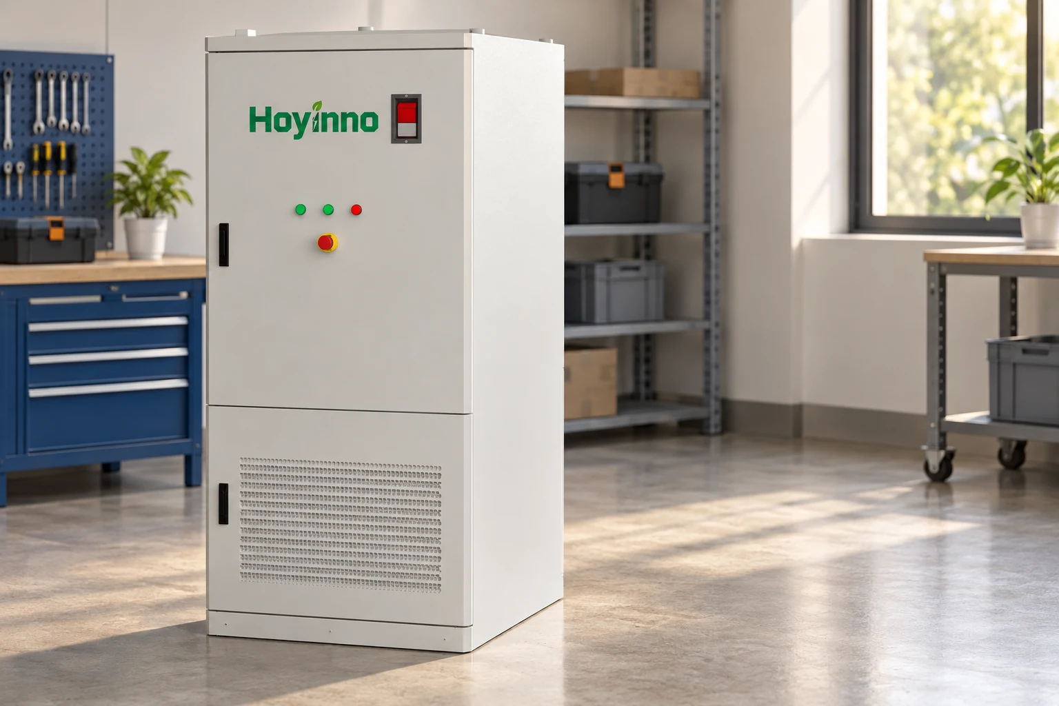
The battery cabinet, power converter and supervisory control system have different jobs. A cabinet may include several integrated components, but the project still needs a clear account of what is included and what is external. The power conversion and control catalogue provides context for the converter role. Compatibility between particular components must be confirmed from their actual specifications and integration documentation.
Understand The AC-Coupled Arrangement
Generation and storage exchange power through an AC boundary
In an AC-coupled arrangement, the photovoltaic system and the battery exchange power through an alternating-current connection. Solar output is converted before it reaches that shared side. Battery charging requires a suitable conversion route into the battery, while discharge requires conversion for the loads or network. This description explains the electrical boundary; it does not establish the performance of any particular converter or a universal efficiency value.
AC coupling can be relevant when storage is added to an existing photovoltaic installation. The existing generation route may remain part of the project, but that does not make every retrofit straightforward. The available connection capacity, equipment behavior, protection and communication need review. An existing inverter that works while the grid is present may not behave the same way in an isolated network. The ability to charge a battery is a different question from the ability to sustain a stable islanded system.
Understand The DC-Coupled Arrangement
A shared DC route changes how solar reaches storage
In a DC-coupled arrangement, generation and storage are connected through a direct-current side of the system. Power conversion is still necessary where the project supplies alternating-current loads or exchanges power with the grid. The equipment must manage the voltage ranges and current limits associated with the connected sources. A shared DC route is an architectural choice, not permission to connect an arbitrary panel string directly to an arbitrary battery.
For a solar and battery system, the architecture must also account for component restrictions. Voltage compatibility, converter capability and manufacturer integration requirements need confirmation. The site energy management information describes monitoring and coordination, but supervisory software cannot remove a physical incompatibility between connected devices. Electrical limits and control permissions need to agree before scheduling strategies are considered.

Compare The Two Routes On The Same Basis
A useful comparison follows one defined energy route at a time. It should use the same site conditions, equipment scope and operating objective for both arrangements. Comparing only advertised capacity can hide different converter ratings or external equipment requirements. Neither architecture should be called inherently suitable without considering the actual installation boundary.
| Dimension | AC-coupled question | DC-coupled question | Evidence needed |
|---|---|---|---|
| Connection boundary | Where does storage join the AC distribution? | Where do generation and storage meet on the DC side? | Single-line diagram and equipment scope |
| Charging route | Which converters handle solar-to-battery flow? | Which devices regulate the shared DC route? | Converter operating ranges and limits |
| Existing equipment | Can the generation equipment operate with the proposed storage controls? | Is the existing array compatible with the proposed DC interface? | Integration and compatibility review |
| Outage behavior | How are AC sources coordinated after isolation? | How is load supply maintained through the required inverter? | Approved islanding and restoration sequence |
| Expansion | Which AC connection limits constrain new equipment? | Which DC voltage, current or converter limits constrain expansion? | Revised architecture and protection study |
| Monitoring | Which meters distinguish generation and battery flows? | Which measurements separate DC routes and AC delivery? | Meter locations and signal definitions |
Connection architecture describes where energy moves, while the control sequence describes when movement is allowed. Those views should agree. A monitoring display can show values without establishing that every route is available. Conversely, a physically possible route may be prohibited by equipment limits, utility requirements or the chosen operating policy. Both the diagram and the approved sequence are needed to interpret system behavior.
Keep Energy Scheduling Separate From Electrical Protection
The supervisory objective operates inside equipment permissions
Energy management may choose when to store surplus generation, reduce grid exchange or preserve an energy reserve. These are operating objectives. The battery and converter also have protective limits that can prevent a requested action. A schedule that requests charging does not mean charging must occur when a device reports a restriction. Understanding the difference prevents a normal protective response from being mistaken for a failure of the scheduling strategy.
The site measurement boundary matters to that strategy. A meter at the utility connection reports a different quantity from a meter on one photovoltaic feeder. If the controller interprets the wrong signal as the complete site exchange, it may respond incorrectly. Meter direction, units, scaling and location need a documented meaning. The design should make it possible to distinguish an actual limit from a measurement or communication problem.
Define Outage And Restoration Behavior Explicitly
Storage availability does not establish backup capability
A battery can contain usable energy while the installation is unable to supply loads during a grid outage. Backup operation depends on isolation, a suitable voltage and frequency reference, compatible conversion equipment and the loads inside the intended boundary. A grid-connected energy-shifting project can have a different design from a project intended to maintain selected loads. The required behavior must be stated before equipment capacity is interpreted as a continuity promise.
The off-grid solution context shows why generation and storage may be coordinated with additional sources. That context is useful, but an off-grid example cannot be transferred automatically to a grid-connected project. Grid restoration introduces its own permissions and checks. Reconnection should follow the approved protection and synchronization arrangements, with responsibility assigned to the equipment and parties involved.
Use Commissioning To Confirm The Installed Architecture
Test the route rather than only the dashboard
Commissioning should connect the documented diagram to observable behavior. The team needs to identify which route is being tested, what condition initiates the action and what result is expected. A dashboard value alone may not show the physical route of energy. Evidence from relevant measurements, device states and control records can establish whether the installed system follows the intended sequence under the test conditions.
Testing should distinguish normal operation from boundary conditions. Solar surplus, low generation, a storage limit and loss of a communication link present different questions. The test plan needs expected behavior and criteria appropriate to each condition. It should also define safe test boundaries and who can authorize changes. This is project-specific engineering work, rather than a universal field procedure that can be carried out from a general article.
The operation and maintenance context is relevant after commissioning because changes can alter the approved behavior. Replacing a converter, updating control software or adding generation may require a review of compatibility and operating permissions. The retained diagram, settings and test record help distinguish an intended modification from an unexplained departure from the commissioned system.
Frequently Asked Questions
Does AC coupling mean the battery stores alternating current?
No. The term describes the connection architecture. The battery's electrical exchange is managed through suitable conversion equipment. The shared AC boundary determines one part of the power route, while the battery remains an electrochemical storage device with its own operating requirements.
Can DC coupling eliminate every conversion stage?
No. A DC-side charging route can change where conversion happens, but alternating-current loads or grid exchange still require suitable equipment. The complete route must be examined under the actual operating condition. Counting one stage in isolation does not establish total system performance.
Can storage be added to any existing solar installation?
That requires a compatibility and connection review. Existing inverter behavior, available electrical capacity, protection and control interfaces may constrain the design. An AC-coupled retrofit is one possible arrangement, but its suitability depends on the installation and the required operating behavior.
Why does a charged battery sometimes fail to provide backup?
Stored energy alone does not establish an isolated supply path. The system needs an approved backup boundary, compatible equipment and the ability to maintain the necessary electrical reference. Some grid-connected storage projects are intended for energy management and have no approved outage-supply function.
What information best explains the complete arrangement?
A single-line diagram, equipment specifications, meter definitions and the operating sequence provide complementary views. A solar and battery system is easier to understand when each energy route, limit and permission can be traced through those documents. A product list alone leaves those relationships unresolved.
The useful conclusion is architectural: first locate the shared electrical boundary, then trace charging and discharge separately, and finally check the controls and protection that permit each route. AC coupling and DC coupling describe connections. The installed equipment, operating sequence and commissioning evidence determine what those connections can actually do.
 Why Do Energy Storage Systems Need More Than A Capacity Figure?
  Address: A401, Junxu Junchuang Park, 03A Qingyi Road, Nanhai District, Foshan City, Guangdong Province, China