



 Home
Home
Where Does Solar Energy Battery Storage Connect To The Power Path?
Solar energy battery storage connects through converters and a defined electrical bus; the connection point determines how solar power reaches the battery and the load.
Trace Electricity Through The System Before Reading The Cabinet Label
The most useful starting point is a path, rather than a product name. Photovoltaic modules produce direct current, batteries store and release energy through a DC interface, and many building loads use alternating current. Converters connect these electrical domains. The arrangement of those converters determines which routes are available during charging and discharge.
Distinguish The Energy Store From Its Electrical Interface
A battery's energy rating describes storage capacity. It does not identify how that battery connects to a solar array, the voltage at a building's distribution board or which loads can operate during an outage. Those questions depend on the inverter or power conversion system, protection equipment, switching and the approved system configuration.
The Department of Energy's storage overview explains the basic distinction between energy capacity and power capacity. It also describes storage as a way to shift energy in time, with losses during conversion and retrieval. These principles explain why a larger energy store does not automatically produce a larger instantaneous output.
Read A Bus As A Shared Connection Point
A bus is a common electrical connection used by several devices. Each route still passes through equipment with ratings, control permissions and protection limits. A system sketch should show permitted energy flows and the devices governing them.
Follow The Solar Route In An AC-Coupled Arrangement
With AC coupling, the solar inverter and the battery's bidirectional converter meet on an alternating-current side of the system. Solar power is converted to AC before the battery converter changes the portion being stored back to DC. Energy serving an AC load directly can take a different path from energy sent through the battery.
Separate Direct Consumption From Stored Solar Energy
Consider daylight operation with a load already running. Part of the solar output can serve that load through the PV inverter. If the system permits charging and has spare capacity, another portion can flow through the battery converter into storage. Later discharge returns battery energy through that converter to the AC side. The diagram therefore needs separate arrows for immediate use, charging and discharge.
AC coupling can suit storage added to existing solar equipment, subject to compatible controls, protection and metering. A grid-connected PV inverter may stop during an outage unless the system supports islanded operation.
The power conversion and control category helps distinguish converter functions from the energy store itself. Product grouping provides a starting point for understanding those roles. The actual single-line diagram must establish which devices are included and where their electrical terminals connect.
Locate The Shared DC Link In A DC-Coupled Arrangement
With DC coupling, solar and battery paths meet on a direct-current side before reaching an AC interface. Depending on the architecture, dedicated DC-to-DC stages manage the PV input and the battery connection. A shared inverter can then supply AC loads or the grid. This describes a family of arrangements, not one universal circuit.
Identify Which Converter Serves Each Direction
A drawing should show whether the PV path, the battery path or both include a DC-to-DC stage. These stages manage electrical compatibility and control within their supported ranges. The fact that two components both use DC does not make a direct connection appropriate. Voltage windows, current limits, isolation requirements and control behavior remain part of the engineered design.
A shared AC inverter also creates a shared output boundary. Available solar power and battery discharge capability cannot simply be added together if both depend on the same constrained conversion stage. The allowed operating combination is determined by the converter and system controls. This matters when interpreting a brochure that lists separate solar, battery and inverter ratings.
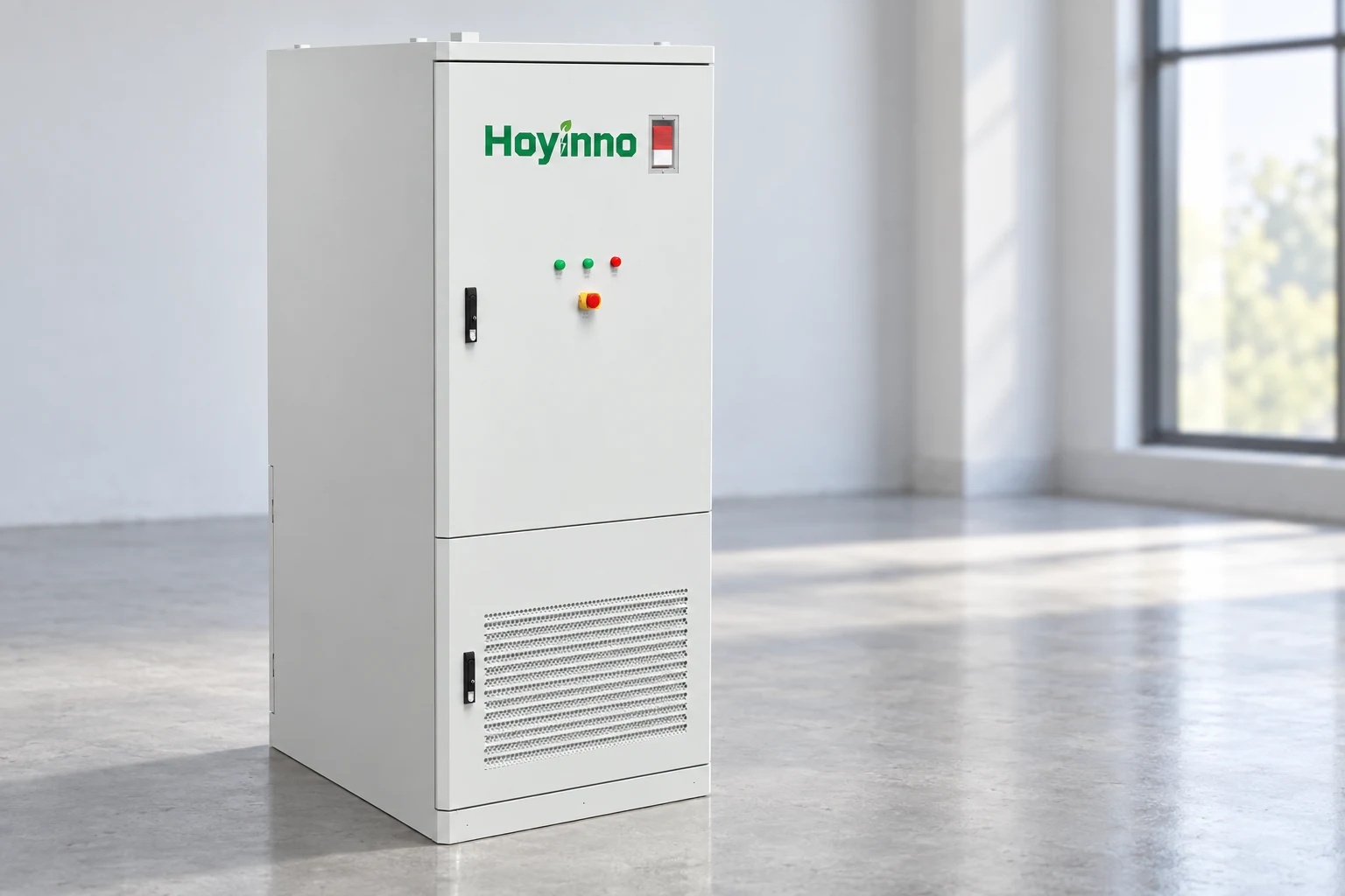
Hoyinno's 233 kWh cabinet page describes an integrated EMS and PCS. Those named functions help explain the difference between supervisory control and electrical conversion. They do not, by themselves, establish every permitted solar input, retrofit configuration or backup operating mode for an individual project.
Compare Routes At The Same Electrical Boundary
A fair comparison follows equivalent energy flows. A single inverter's peak efficiency and a complete stored-energy cycle have different boundaries. Charging, auxiliary consumption and later discharge affect the latter.
| Question | AC-side meeting point | DC-side meeting point | What the diagram must show |
|---|---|---|---|
| Where do solar and battery paths join? | On an AC bus after their converters | On a DC link before the AC interface | The actual common connection |
| How is solar sent to the battery? | Through PV inversion and battery conversion | Through the designed DC charging path | Every conversion stage in that route |
| Which device limits AC output? | Separate converters plus site limits | A shared inverter in common designs | Equipment and connection-point ratings |
| Can existing solar remain? | Potentially, subject to compatibility | May require changes to the DC architecture | Existing interfaces and required alterations |
| Does the label guarantee backup? | No | No | Island formation, switching and supported loads |
Keep Efficiency Claims Attached To A Defined Route
The DOE Solar-Plus-Storage 101 explanation distinguishes separate and shared inverter arrangements. Neither architecture deserves a blanket efficiency claim without the operating point, equipment and measurement boundary being specified.

Keep Control Messages Separate From Power Conductors
Control systems determine desired behavior, while electrical equipment carries and converts energy. An energy management system can request charging, limit export or preserve a reserve, but it cannot create a missing electrical route. A communications connection and a power connection therefore answer different questions on a system drawing.
Understand The Roles Of EMS, BMS And PCS
The EMS coordinates operation at a supervisory level. The battery management system monitors and protects the battery within its design, while the PCS handles electrical conversion within its limits. Their responsibilities overlap at interfaces, so commands, reported states and protective restrictions must be understood together. A requested discharge can be reduced or refused when the battery or converter cannot support it.
The site's EMS information offers context for monitoring and operating coordination. A dashboard image alone does not prove compatible communications or successful control of an existing inverter. Those capabilities depend on the supported devices, interfaces and commissioned configuration. Monitoring a value and controlling the equipment that produces it are distinct functions.
For solar energy battery storage, the control story should also explain unavailable information. If a meter or communications link is lost, the system needs a defined response. A description that assumes every signal is always healthy leaves an important operating condition unexplained. The response must come from the engineered system, rather than from a generic promise of smart control.

Explain What Changes When The Grid Is Absent
An outage changes the electrical reference and the permissible paths. Equipment that operates while connected to a stable grid may not be able to establish an independent supply. Backup requires a supported arrangement for separating the intended loads from the grid and maintaining the electrical conditions those loads need.
Distinguish Grid Following From Islanded Operation
A grid-following device normally works with an existing voltage and frequency reference. An island needs equipment and controls capable of establishing and regulating that reference within the designed limits. The labels solar inverter and battery cabinet do not settle this question. A system may include storage for energy shifting while supporting no islanded supply at all.
Hoyinno's off-grid solution information describes a different operating context from ordinary grid-connected storage. It should be read alongside the specific system design, including startup sequence, supported sources and load boundaries. A general solution page cannot confirm how an existing site's protection and transfer arrangement will behave.
Use Equipment Pages To Name Functions, Then Reconstruct The System
A cabinet can combine battery modules, conversion and controls. Integration changes the enclosure boundary while leaving the electrical interfaces essential to understanding the system.
Read Integration As A Scope Statement
Hoyinno's 522 kWh cabinet description lists several integrated functions, including battery management, conversion and solar-related components. The exact supplied configuration still needs to be established for the application. An enclosure photograph cannot verify internal wiring, protection coordination or an available input specification that the order does not identify.
The engineering service page places integration in context. A single-line diagram and operating-mode description should connect the equipment list to a coherent system with explicit service boundaries.
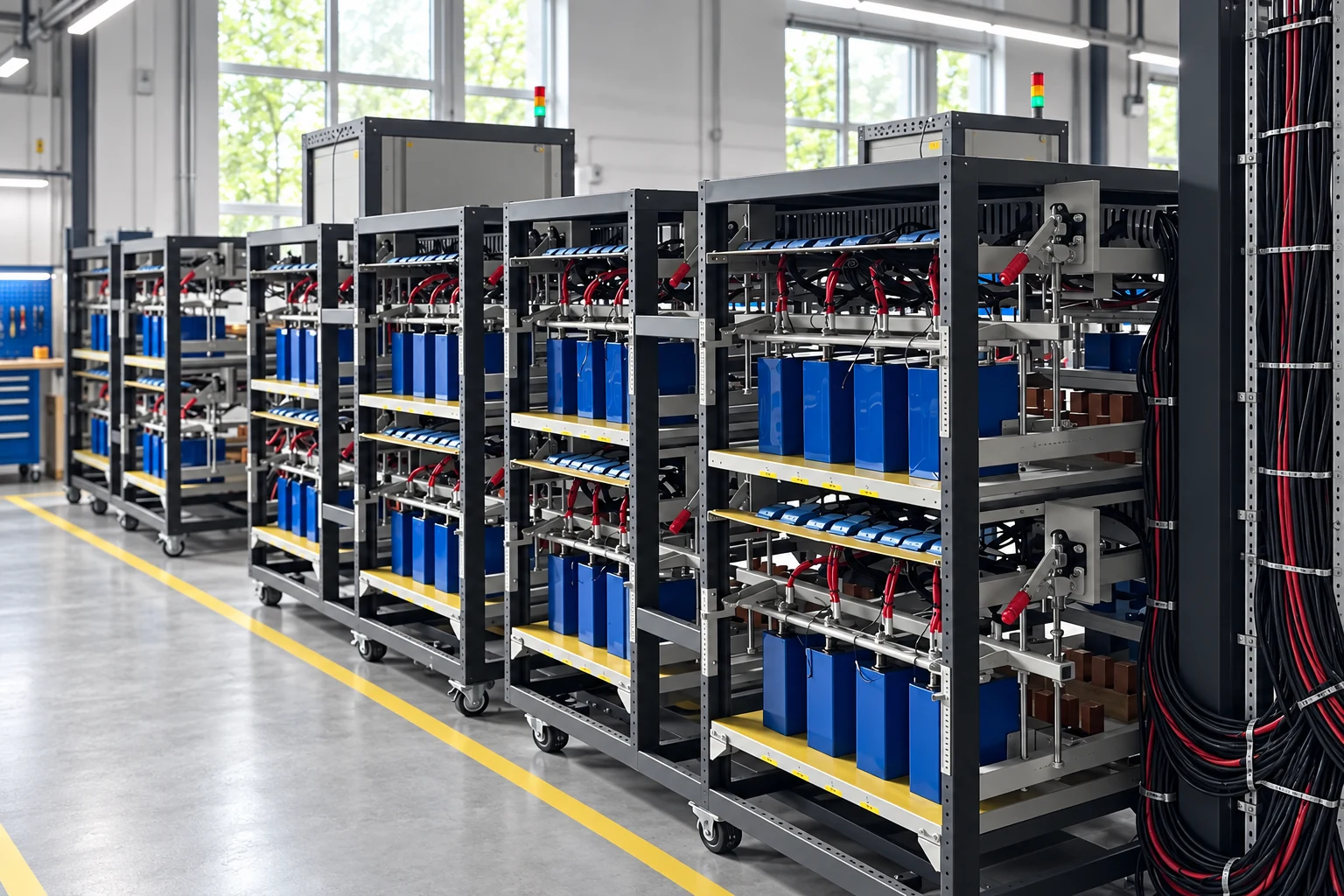
When reading solar energy battery storage documentation, start at the panels and follow each route to the load, battery and grid. Mark the conversion stages, the limits shared by multiple routes and the devices responsible for each operating mode. The resulting understanding is more reliable than inferring functionality from enclosure size or a single capacity figure.
Frequently Asked Questions
Does A Battery Store Alternating Current?
A battery stores energy chemically and connects electrically through DC terminals. An AC-connected storage system includes conversion equipment between those terminals and the AC network. The system's connection label describes the interface, not a different form of stored current.
Does DC Coupling Mean There Is No Inverter?
No. An inverter is still needed when the system supplies AC loads or an AC grid. The term identifies where the solar and battery routes meet; it does not remove the need for conversion between electrical domains.
Can Two Converter Ratings Be Added To Find Site Output?
Only if the engineered arrangement permits that combination within all shared limits. A common inverter, transformer, connection agreement or control limit can constrain simultaneous output. Nameplate values alone do not establish the available combined power.
Can AC Coupling Provide Backup During An Outage?
It can in a suitably designed system, but the topology name alone does not establish that capability. Supported island formation, switching, protection and compatible solar-inverter behavior must be part of the actual configuration.
Why Is A Single-Line Diagram More Useful Than A Cabinet Photo?
The photograph identifies visible equipment. The diagram shows how electrical functions connect, where limits apply and which routes exist. Both have a role, but only the defined system documentation can explain the intended operating paths.
The essential distinction is the meeting point between solar and storage, followed by the conversion and control needed around it. Once those boundaries are clear, equipment descriptions become easier to interpret without confusing energy capacity, electrical output and backup capability.
 Solar And Battery Storage Follow Priorities Set By The Operating Mode
  Address: A401, Junxu Junchuang Park, 03A Qingyi Road, Nanhai District, Foshan City, Guangdong Province, China