



 Home
Home
Which Design Logic Makes A Microgrid Energy Storage Solution Resilient?
A Microgrid Energy Storage Solution works when its power, energy, controls, protection, thermal design, and commissioning plan derive from defined loads and operating modes. Storage is not an isolated battery purchase: it becomes useful only as part of a controllable electrical boundary that coordinates local generation, demand, the utility connection, and islanded operation.
Start With the Microgrid Operating Objective
A resilient design begins with the service the microgrid must deliver. DOE describes interconnected loads and local resources within a defined boundary that act as one controllable entity with respect to the grid. The design must decide which loads are inside, when the system disconnects, which resources remain available, and what each state must achieve.
Define Boundaries, Modes, and Success Criteria Together
The electrical boundary should be drawn on the single-line diagram, not left as a narrative. The design basis should name grid-connected, transition, islanded, resynchronization, black-start if required, and maintenance modes. For each mode, it should state permitted sources, load priorities, voltage and frequency expectations, transition behavior, reserve policy, and duration. These criteria determine whether storage must follow an external grid reference or help establish one.
Build the Critical Load Profile Before Selecting Capacity
A critical load profile separates essential circuits from deferrable or shed loads and shows power over time, not just an annual energy total. Record normal demand, peak demand, motor starts, step changes, power factor, harmonics, daily shape, seasonal variation, restoration sequence, and minimum service duration. The same peak can require very different storage when one site needs seconds of ride-through and another needs hours of islanded operation.
| Design input | Question to answer | Storage implication | Evidence needed |
|---|---|---|---|
| Operating modes | When is the utility present, absent, or being resynchronized? | Control mode, transition speed, reserve, grid-forming capability | Mode narrative and single-line diagram |
| Critical loads | Which loads must run, start, or shed in each mode? | Power rating, surge duty, usable energy, dispatch priority | Interval data and load-step list |
| Local generation | What is controllable, variable, or unavailable? | Charging window, curtailment, ramping, energy balance | Resource profiles and controller interfaces |
| Site conditions | What temperatures, humidity, dust, altitude, access, and space apply? | Derating, cooling, enclosure, layout, maintenance clearance | Site survey and environmental basis |
| Acceptance | How will transitions, autonomy, protection, and dispatch be proven? | Instrumentation, test sequence, pass criteria, data retention | Commissioning and performance test plan |
Convert Load Behavior Into Power and Energy
A Microgrid Energy Storage Solution must calculate power and energy separately. Power addresses demand, ramp rate, inrush, frequency support, and converter limits. Energy addresses how long that power can be sustained after state-of-charge limits, auxiliaries, temperature, aging allowance, and recovery policy. Nameplate energy alone cannot prove the required event.
Size Power for the Hardest Credible Moment
The hardest moment may be a large motor start, a generation trip, a rapid renewable ramp, an islanding transition, or simultaneous restoration of several loads. Time-series and dynamic studies should identify the event and its duration. Converter overload capability, battery current limits, voltage behavior, and protection settings must be checked together. Oversizing energy will not repair a converter that cannot deliver the required short-duration power.
Size Usable Energy Around a Dispatch Envelope
Energy sizing should model starting state of charge, minimum and maximum limits, efficiency, auxiliary demand, degradation allowance, forecast uncertainty, and the chance to recharge. A battery dispatch strategy also needs priorities: peak reduction, renewable capture, tariff response, spinning reserve, outage readiness, or some combination. If daily economic cycling consumes the reserve needed for resilience, the controller must preserve or restore the required margin before a credible event.
Design the Control Stack Before Writing the Schedule
Microgrid performance depends on coordinated control layers. Device controllers protect batteries and power electronics; a plant or microgrid controller balances sources and loads; supervisory energy management functions optimize schedules and exchange data with operators or external systems. The hierarchy should define ownership of every command, measurement, limit, alarm, fallback state, and time scale.
Distinguish Grid-Following From Grid-Forming Responsibilities
In grid-connected operation, a converter may follow voltage and frequency established by the utility or another source. In islanded operation, the microgrid needs a resource and control scheme capable of establishing stable voltage and frequency, sharing power, and managing disturbances. Island mode controls must also coordinate load shedding, generator start, renewable curtailment, state-of-charge protection, and resynchronization. The required function must be confirmed for the selected equipment and system architecture.
Make Dispatch Rules Observable and Testable
A battery dispatch strategy should translate objectives into measurable setpoints, constraints, priorities, and fallback behavior. Operators need to see the current mode, available power and energy, reserve margin, active limits, alarm state, and reason for curtailed or shed load. Communications loss should lead to a defined safe state rather than an undocumented default. Time synchronization and event logs are essential for proving what happened during a transition.
Coordinate Protection, Communications, and Interfaces
Protection cannot be copied unchanged from a grid-connected feeder because fault current may change when the microgrid islands or relies on inverters. Communications also become operational risk when dispatch, protection, metering, or support depend on data links. Develop these interfaces with the power and control studies, not after equipment selection.
Study Faults in Every Credible Network State
Protection studies should cover utility-connected and islanded configurations, different generation combinations, breaker states, grounding arrangements, and inverter fault behavior. Settings, zones, selectivity, detection methods, and transfer logic must still protect equipment and people while avoiding unnecessary loss of critical loads. A design may need mode-adaptive settings, differential protection, additional sensing, or a revised grounding and neutral strategy.
Specify Data as an Engineering Interface
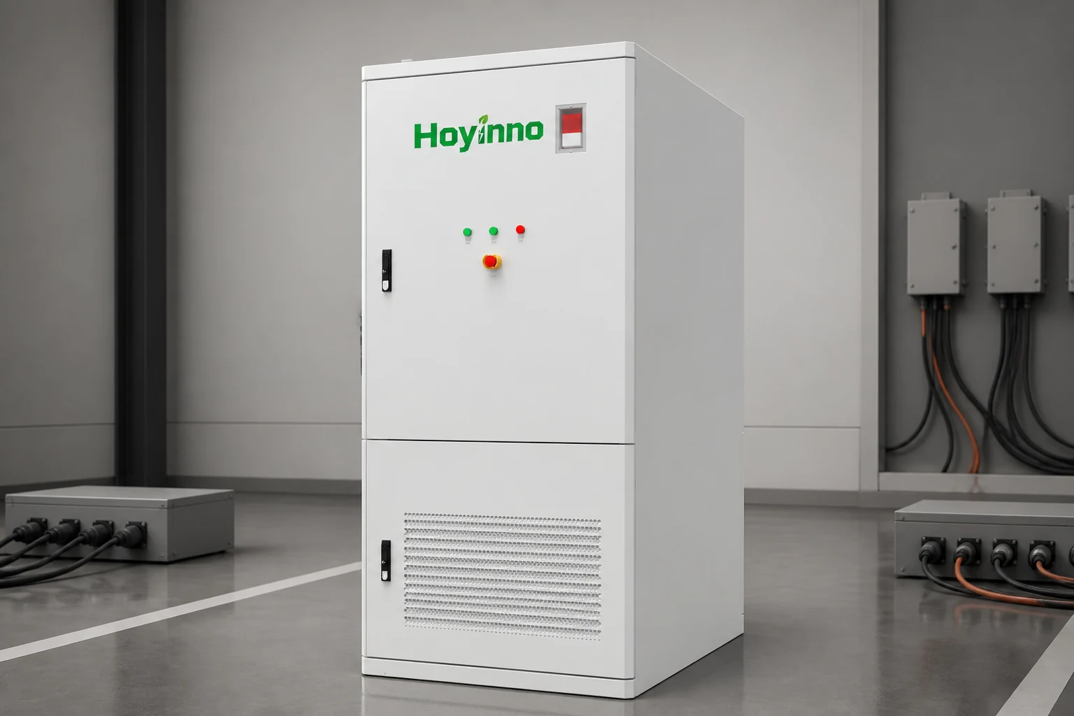
Each exchanged point should have a source, unit, update rate, range, quality flag, time stamp, ownership rule, and behavior on loss. The same discipline applies to commands and alarms. The 129 kWh cabinet page lists RS485, Modbus TCP/IP, and an EMS cloud platform as product-page features; project compatibility still depends on the exact point list, protocol implementation, cybersecurity design, and controller responsibility.
Fit the Physical System to the Site
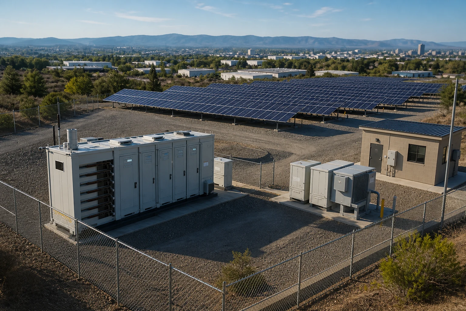
A correct energy model can fail in a poor physical arrangement. Temperature, humidity, dust, salt, flooding, altitude, solar exposure, ventilation, noise, fire strategy, access, lifting, cable entry, drainage, and clearance influence equipment and layout. The remote-area solution page and commercial application page show contexts, but the site survey must define actual conditions.
Connect Thermal Design to Duty Cycle and Maintenance
Cooling should be evaluated against local extremes, expected cycling, heat rejection, auxiliary power, redundancy, alarms, and degraded modes. Temperature uniformity can affect available power, aging, and protection behavior, while dirty filters or blocked airflow can change performance after commissioning. Maintenance planning should name inspection intervals, consumables, isolation steps, safe access, spare strategy, and the data used to detect declining thermal performance.

Prove the Design Through Staged Commissioning
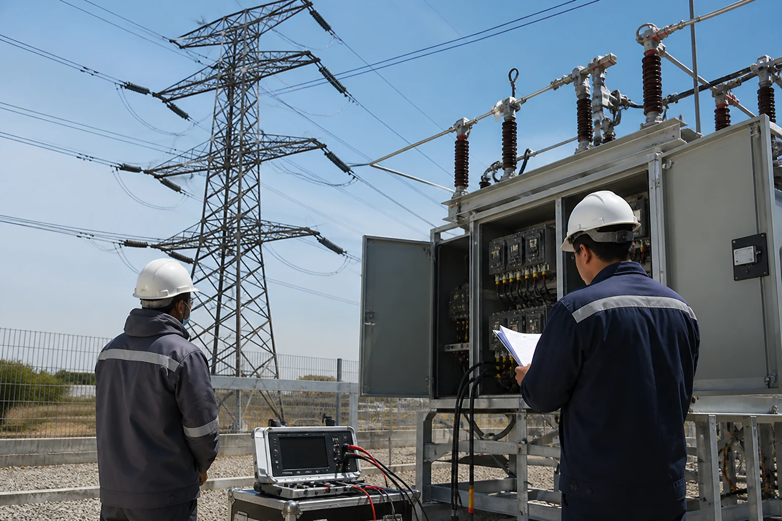
Commissioning should demonstrate the operating concept rather than merely confirm that devices energize. Start with document and factory checks, then verify installation, point-to-point signals, protections, device controls, plant controls, transitions, dispatch, alarms, fallback states, and performance. The same-site engineering service overview can frame responsibilities, while DOE project guidance treats planning, design, procurement, implementation, and distributed-energy checklists as connected phases; the acceptance plan should do the same.
Write Microgrid Commissioning Tests From Requirements
Microgrid commissioning tests should trace every step to an agreed requirement and identify prerequisites, instrumentation, initial conditions, sequence, expected response, tolerances, safety hold points, evidence capture, and approval authority. Include loss of grid, failed transition, load steps, resource trips, communications loss, low and high state-of-charge limits, restoration, resynchronization, emergency stop, and recovery from protected states when those scenarios belong to the design basis.
Acceptance data should show whether power, duration, stability, response time, thermal behavior, and reserve policy met the specified conditions. Deviations need disposition before final approval. Operators should receive the single-line diagram, mode logic, alarm response, maintenance boundaries, safe shutdown and restart procedures, access controls, and a clear path for technical escalation. The service page can frame support discussions, but project deliverables should be explicit.
Frequently Asked Questions
Is battery capacity the main microgrid design decision?
No. A Microgrid Energy Storage Solution derives capacity from operating modes, critical loads, power events, local generation, controls, protection, site conditions, maintenance, and acceptance criteria. A large battery with the wrong converter or control architecture can still fail the duty.
How is a critical load profile different from a utility bill?
A utility bill summarizes consumption and demand for billing, while a critical load profile identifies time-dependent essential loads, starting events, step changes, priorities, shedding sequence, restoration order, and required duration during each operating mode. Interval and event data are usually needed.
Does every storage system need grid-forming capability?
Not necessarily. A grid-connected system may follow an external reference, and an islanded system may use another grid-forming source. The architecture must identify which resource establishes voltage and frequency in every mode and how other resources coordinate with it.
Why are commissioning tests defined before procurement?
Early test definitions make performance requirements measurable and expose missing interfaces before contracts are signed. They help bidders price instrumentation, software, site work, and support consistently, and they reduce disputes about what counts as a successful transition or dispatch response.
What should be confirmed before asking for a system proposal?
Provide the single-line boundary, critical load profile, resource data, operating modes, resilience duration, site conditions, interconnection constraints, control and protocol expectations, protection basis, commissioning scenarios, and required deliverables. Unknown items should be labelled for study rather than replaced with assumptions.
The strongest design is not the one with the largest nameplate. It is the one whose control boundary, power and energy envelope, protection, site fit, and test evidence remain coherent in every required mode.
 How Does An Off Grid Solar Battery Storage System Balance Loads And Autonomy?
  Address: A401, Junxu Junchuang Park, 03A Qingyi Road, Nanhai District, Foshan City, Guangdong Province, China